
LINACT-35
High-Force Linear Actuator
The LINACT-35 Linear Actuator is a high-performance electric actuator designed for demanding industrial, agricultural, construction and equipment automation applications requiring higher loads, advanced control options and robust environmental protection.
Available with both Acme screw and ball screw configurations, the LINACT-35 can deliver dynamic loads of up to 17,000 N and self-locking force of up to 20,000 N, depending on the selected configuration. Selected ball-screw variants offer duty cycles of up to 35%, while IP66 protection, manual override and a wide range of feedback and control options allow the actuator to be configured around the application’s operating requirements.
The LINACT-35 range is built to specification and is not normally stocked. Each actuator is selected according to the required load, speed, stroke, voltage, mounting arrangement, feedback and control requirements.
Detailed Specifications of the LINACT-35 Linear Actuator
The LINACT-35 Linear Actuator is a high-performance electric actuator designed for demanding applications requiring higher load capability, advanced feedback and control options, and robust environmental protection.
The LINACT-35 is available with both Acme screw and ball screw configurations, allowing the actuator to be selected according to the required balance of load, speed, duty cycle and efficiency. Depending on the selected configuration, the LINACT-35 can provide dynamic loads of up to 17,000 N and self-locking capacity of up to 20,000 N.
Stroke lengths are configurable up to 1,000 mm, subject to the selected gearset, load, speed and application requirements. Selected ball-screw variants offer a duty cycle of up to 35%, while the wider range includes both 20% and 35% duty-cycle configurations depending on the selected model.
The LINACT-35 offers a broad selection of feedback and control options, including end-stop signal, Hall Effect Sensor, analog signal and magnetic switches. Control options include logic level control, SK523D controller compatibility, synchronized control and CAN bus control.
Additional features include IP66 environmental protection, electronic overload protection and a standard manual override for emergency operation when electrical power is unavailable.
The LINACT-35 range is built to specification and is not normally stocked. Each actuator should be selected according to the required load, speed, stroke, duty cycle, voltage, mounting arrangement, feedback and control requirements.
General Technical Specifications of the LINACT-35 Linear Actuator
The LINACT-35 Linear Actuator is a highly configurable industrial actuator designed to be matched to the required load, speed, stroke, voltage, mounting arrangement, feedback and control requirements of the application.
The LINACT-35 is available with both Acme screw and ball screw configurations. Depending on the selected version, it can provide dynamic loads of up to 17,000 N and self-locking force of up to 20,000 N, with full-load speeds ranging from approximately 5 mm/s to 23 mm/s.
Selected ball-screw configurations offer a duty cycle of up to 35%, while other variants operate at 20%. Stroke lengths are configurable up to 1,000 mm, although the maximum available stroke can depend on the selected force, speed and application requirements.
The LINACT-35 offers advanced feedback and control capability, including end-stop signal, Hall Effect Sensor, analog signal and magnetic switches. Control options include polarity switching, logic level control, SK523D controller compatibility, synchronized control and CAN bus control.
The LINACT-35 is supplied with IP66 environmental protection, electronic overload protection and a manual override for emergency operation when electrical power is unavailable.
The LINACT-35 range is built to specification and is not normally stocked. Final configuration should be selected according to the actual application and operating conditions.
| Specification | LINACT-35 |
|---|---|
| Motor Type | Brushed DC |
| Lead Screw Options | Acme Screw or Ball Screw |
| Available Voltages | 12VDC, 24VDC, 36VDC, 48VDC |
| Maximum Dynamic Load | Up to 17,000 N |
| Maximum Self-Locking Force | Up to 20,000 N |
| Full-Load Speed Range | Approximately 5 to 23 mm/s, depending on configuration |
| Stroke Range | Up to 1,000 mm, depending on configuration and application |
| Duty Cycle | 20% or up to 35% depending on selected configuration |
| Weather Protection | IP66 |
| Operating Noise | ≤65 dB |
| Operating Temperature | -10°C to +65°C, with extended -40°C to +65°C option |
| Position Feedback Options | End-stop Signal, Hall Effect Sensor, Analog Signal, Magnetic Switches |
| Control Options | Polarity Switching, Logic Level, SK523D, Synchronized Control, CAN bus |
| Overload Protection | Electronic |
| Manual Override | Standard |
| Availability | Built to specification – not normally stocked |
LINACT-35 specifications vary according to the selected gearset, lead screw, stroke, voltage and control configuration. Final actuator selection should always be based on the actual application requirements.
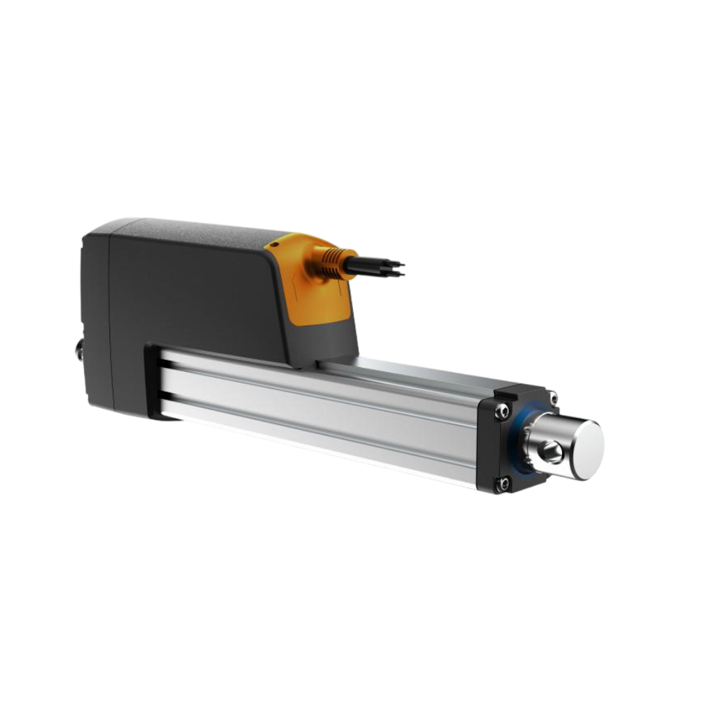

LINACT-35 Performance Variants
The LINACT-35 Linear Actuator is available in multiple performance configurations, allowing the actuator to be selected according to the required balance of load, speed, duty cycle and lead-screw type. Ball-screw variants provide higher transmission efficiency and selected configurations offer up to a 35% duty cycle, while Acme-screw variants provide robust self-locking performance across a wide load range.
| Code | Lead Screw | Duty Cycle | Max Dynamic Force | Self-Locking Force | Screw Pitch | Free-Load Speed | Full-Load Speed | Max Stroke at Full Capacity |
|---|---|---|---|---|---|---|---|---|
| A | Ball Screw | 20% | 17,000 N | 20,000 N | 5 mm | 6.5 mm/s | 5 mm/s | 600 mm* |
| B | Ball Screw | 35% | 13,500 N | 15,000 N | 5 mm | 9 mm/s | 6.5 mm/s | 1,000 mm |
| C | Ball Screw | 35% | 10,000 N | 12,000 N | 5 mm | 14 mm/s | 9 mm/s | 1,000 mm |
| D | Ball Screw | 35% | 7,500 N | 10,000 N | 10 mm | 18 mm/s | 13 mm/s | 1,000 mm |
| E | Ball Screw | 35% | 5,000 N | 8,000 N | 10 mm | 28 mm/s | 20 mm/s | 1,000 mm |
| F | Acme Screw | 20% | 12,000 N | 15,000 N | 4 mm | 7 mm/s | 5 mm/s | 1,000 mm |
| G | Acme Screw | 20% | 10,000 N | 12,000 N | 8 mm | 10 mm/s | 7 mm/s | 1,000 mm |
| H | Acme Screw | 20% | 7,500 N | 10,000 N | 8 mm | 14 mm/s | 8 mm/s | 1,000 mm |
| I | Acme Screw | 20% | 5,000 N | 8,000 N | 8 mm | 23 mm/s | 13 mm/s | 1,000 mm |
| J | Acme Screw | 20% | 3,500 N | 5,000 N | 12 mm | 35 mm/s | 23 mm/s | 1,000 mm |
Choosing the correct LINACT-35 configuration: Higher-force variants generally operate at lower speeds, while faster variants provide lower maximum force. Ball-screw configurations B to E offer a higher duty cycle of up to 35%, while Code A and the Acme-screw configurations operate at 20%.
The required actuator should therefore be selected according to the actual combination of load, speed, stroke, duty cycle and application requirements, rather than load capacity alone.
*Code A provides its full 17,000 N dynamic load capacity up to a 600 mm stroke. For strokes from 601 mm to 1,000 mm, the catalogue specifies a reduced maximum force of 14,500 N. Performance values are based on testing with a stable power supply at an ambient temperature of 20°C.
Fully Extended & Fully Retracted Lengths
The LINACT-35 Linear Actuator is built to specification, and its overall installation length depends on the selected stroke, performance code and mounting-end configuration. The dimensions below provide reference installation lengths based on the LINACT-35 CAD configurations shown.

A = Stroke Length | B = Fully Retracted Length | C = Fully Extended Length
The stroke length is the actuator travel. Fully retracted and fully extended lengths are measured centre-to-centre between the actuator mounting points.
Reference CAD Configurations:
50–600 mm stroke: F07 / R02 mounting with Ø30 mm rod
700–1000 mm stroke: F02 / R02 mounting with Ø35 mm rod
| Stroke Length | Fully Retracted Length* | Fully Extended Length* |
|---|---|---|
| 50 mm | 300 mm | 350 mm |
| 100 mm | 300 mm | 400 mm |
| 200 mm | 400 mm | 600 mm |
| 300 mm | 500 mm | 800 mm |
| 400 mm | 650 mm | 1050 mm |
| 500 mm | 750 mm | 1250 mm |
| 600 mm | 850 mm | 1450 mm |
| 700 mm | 1000 mm | 1700 mm |
| 800 mm | 1100 mm | 1900 mm |
| 900 mm | 1200 mm | 2100 mm |
| 1000 mm | 1300 mm | 2300 mm |
Alternative Configuration – Installation Length Adjustments:
The LINACT-35 is built to specification. Different performance codes and mounting ends may therefore require a longer installation length than the reference CAD configurations shown above.
- Performance Codes A and B: require an additional 30 mm installation allowance.
- Stroke 301–600 mm: requires an additional 50 mm compared with the basic stroke + 200 mm calculation.
- Stroke 601–1000 mm: requires an additional 100 mm.
- Front mounting ends F13 and F14: require an additional 40 mm.
- For F01–F12 configurations with strokes of 100 mm or less, the catalogue specifies a minimum installation length of 300 mm.
*The dimensions in the table correspond to the reference LINACT-35 CAD configurations shown above: F07/R02 with Ø30 mm rod for 50–600 mm strokes and F02/R02 with Ø35 mm rod for 700–1000 mm strokes. Final installation dimensions must be confirmed against the selected LINACT-35 configuration before manufacture or installation.
Key Features & Benefits
The LINACT-35 Linear Actuator is designed for demanding applications that require higher load capacity, increased efficiency and more advanced feedback and control options. Its combination of robust construction, flexible configuration and IP66 protection makes it well suited to industrial machinery, mobile equipment and OEM automation systems.
- High Dynamic Load Capacity: LINACT-35 configurations are available with dynamic load capacities up to 17,000 N, providing substantial pushing and pulling force for demanding automation and machinery applications.
- Up to 20,000 N Self-Locking Force: Selected LINACT-35 configurations can hold static loads of up to 20,000 N, helping the actuator maintain position securely when stopped.
- Acme Screw & Ball Screw Options: The LINACT-35 is available with both Acme screw and ball screw configurations, allowing the actuator to be selected according to the required balance of force, speed, efficiency and duty cycle.
- Up to 35% Duty Cycle: Selected ball-screw LINACT-35 variants offer a duty cycle of up to 35%, making them suitable for applications requiring more frequent operation than lower-duty-cycle actuator ranges.
- IP66 Environmental Protection: The LINACT-35 is designed with IP66 protection for reliable operation in dusty, wet and demanding industrial or outdoor environments.
- Advanced Position Feedback Options: Available feedback options include end-stop signal, Hall Effect Sensor, analog signal and magnetic switches, providing flexible solutions for position monitoring and control.
- Advanced Control Options: The LINACT-35 can be configured for polarity switching, logic level control, SK523D controller operation, synchronized control and CAN bus control.
- Manual Override: A standard manual override allows the LINACT-35 to be extended or retracted mechanically in emergency situations where electrical power is unavailable.
- Electronic Overload Protection: Electronic overload protection helps protect the actuator and equipment from excessive loading conditions.
- Wide Voltage Selection: The LINACT-35 is available in 12VDC, 24VDC, 36VDC and 48VDC configurations for integration into a wide range of machines and electrical systems.
- Configurable Stroke Lengths: LINACT-35 configurations are available with stroke lengths up to 1,000 mm, subject to the selected force, speed and application requirements.
- Built-to-Spec Flexibility: The LINACT-35 is not normally stocked and is configured according to the required load, speed, stroke, voltage, mounting arrangement, feedback, control and operating conditions.
Typical Applications
The LINACT-35 Linear Actuator is suited to demanding applications requiring higher load capacity, robust construction and more advanced control or feedback options. Its configurable design makes it suitable for a wide range of industrial, agricultural, equipment and OEM applications, including:
- Industrial Machinery & Automation: Suitable for lifting, positioning, opening, closing and adjustment functions on production machinery, material-handling equipment and automated systems requiring higher force and reliable linear movement.
- Agricultural Machinery & Implements: The LINACT-35 can be used on heavy agricultural equipment for positioning, adjustment, lifting and opening mechanisms where higher loads or more demanding operating conditions are involved.
- Construction & Heavy Equipment: Suitable for engine hoods, access panels, service covers, lifting mechanisms and adjustment functions on construction, mining and earthmoving equipment.
- Lifting & Positioning Systems: The higher load capacity and wide range of control options make the LINACT-35 suitable for selected lifting and positioning systems where controlled electric movement is required.
- Patient Hoist & Assisted-Lifting Applications: The LINACT-35 has also been supplied for a patient-hoist application, demonstrating its versatility in specialised lifting systems. Suitability for any patient-handling or medical application must be evaluated against the specific load, safety, control and regulatory requirements of the complete system.
- Outdoor & Mobile Equipment: With IP66 protection, the LINACT-35 can be considered for machinery and equipment exposed to dust, moisture and demanding outdoor operating environments.
- Position-Controlled Systems: Feedback options including Hall Effect Sensor, analog signal and magnetic switches allow the LINACT-35 to be integrated into applications requiring position monitoring or controlled movement.
- Synchronized Multi-Actuator Systems: The LINACT-35 can be configured for synchronized control, making it suitable for selected applications requiring two or more actuators to operate together.
- Custom Machinery & OEM Applications: Because the LINACT-35 is built to specification, it is particularly well suited to OEM equipment and purpose-built machinery where the actuator needs to be matched to specific load, speed, stroke, mounting, feedback and control requirements.
Application selection is important: LINACT-35 configurations vary significantly in load, speed, duty cycle, mounting and control capability. Final actuator selection should therefore be based on the actual operating conditions and requirements of the complete application.
Mounting Brackets
Mounting Options
The LINACT-35 Linear Actuator offers a wide selection of front and rear mounting configurations, allowing the actuator to be matched to different machinery, equipment and installation requirements.
Available LINACT-35 front mounting options include F01 to F14, with a choice of through-hole, threaded and joint-bearing style connections. Rear mounting options include R01 to R07, providing additional flexibility when integrating the actuator into equipment or custom machinery.
Mounting-hole orientation can also be selected to suit the installation. Because the selected front and rear mounting ends can affect the actuator’s overall installation length, the final mounting configuration should be confirmed when specifying the LINACT-35.
For additional actuator mounting hardware and accessories, visit our
Linear Actuator Accessories
page, or contact Linear Actuators South Africa to confirm the correct mounting arrangement for your LINACT-35 configuration.
Download Data Sheet
Get the technical information required to specify the correct LINACT-35 Linear Actuator. The official LINACT-35 product overview includes configuration options, load and speed performance, mounting dimensions, feedback options, control modes, manual override details and ordering information.
Download LINACT-35 Product Overview
Technical Document Notice: Technical information and product documentation are provided for product selection and reference purposes. Copyright and intellectual property rights remain with their respective owner. Documents may not be altered, reproduced or distributed for commercial purposes without the appropriate permission. Supply of LINACT-35 products by Linear Actuators South Africa is subject to our Standard Terms & Conditions .
Video Demonstration
Video Demonstration: LINACT-35 Linear Actuator
Take a closer look at the LINACT-35 Linear Actuator. This video provides a practical view of the actuator and its operation, helping customers better understand the size, construction and movement of the LINACT-35.
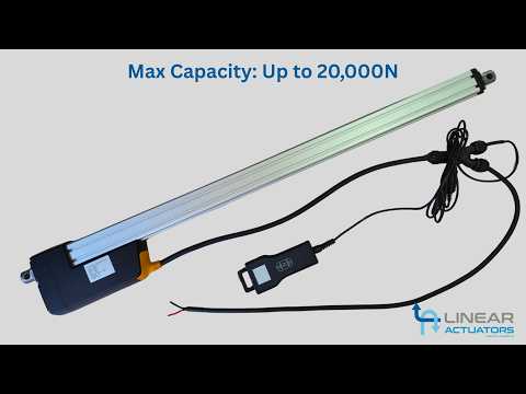
Video Demonstration: LINACT-35 in Operation
See the LINACT-35 Linear Actuator in operation. This video gives a closer look at the actuator’s linear movement and provides a useful reference for customers considering the LINACT-35 for industrial machinery, lifting, positioning or custom automation applications.
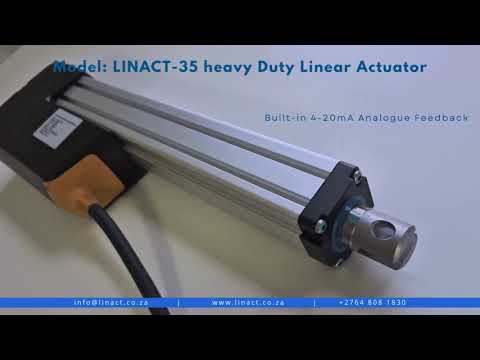
Download 3D Models
For engineers and designers, precise planning is essential. Download our comprehensive LINACT-35 linear actuator 3D drawings for standard stroke lengths. These detailed STEP models allow you to integrate the actuator into your designs for accurate visualisation, dimensional planning and advanced project development.
LINACT-35 Standard 3D Models:
50–600mm stroke: F07 / R02 mounting with Ø30mm rod | 700–1000mm stroke: F02 / R02 mounting with Ø35mm rod
LINACT-35 50mm Stroke – F07/R02 – Ø30mm Rod (STP)
LINACT-35 100mm Stroke – F07/R02 – Ø30mm Rod (STP)
LINACT-35 200mm Stroke – F07/R02 – Ø30mm Rod (STP)
LINACT-35 300mm Stroke – F07/R02 – Ø30mm Rod (STP)
LINACT-35 400mm Stroke – F07/R02 – Ø30mm Rod (STP)
LINACT-35 500mm Stroke – F07/R02 – Ø30mm Rod (STP)
LINACT-35 600mm Stroke – F07/R02 – Ø30mm Rod (STP)
LINACT-35 700mm Stroke – F02/R02 – Ø35mm Rod (STP)
LINACT-35 800mm Stroke – F02/R02 – Ø35mm Rod (STP)
LINACT-35 900mm Stroke – F02/R02 – Ø35mm Rod (STP)
LINACT-35 1000mm Stroke – F02/R02 – Ø35mm Rod (STP)
Intellectual Property Notice:
All 3D drawings and technical specifications remain the exclusive property of Linear Actuators South Africa (Pty) Ltd. These files may not be reproduced or shared
without written consent, in accordance with Clause 16 of our